ANCEL PB100 Automotive Circuit Tester – Power Probe Kit for 12V/24V Electrical System Diagnostics
ANCEL PB100 Automotive Circuit Tester – Power Probe Kit for 12V/24V Electrical System Diagnostics
Couldn't load pickup availability
SPECIFICATIONS
Brand Name: ANCEL
Certification: CE
Choice: yes
Origin: Mainland China

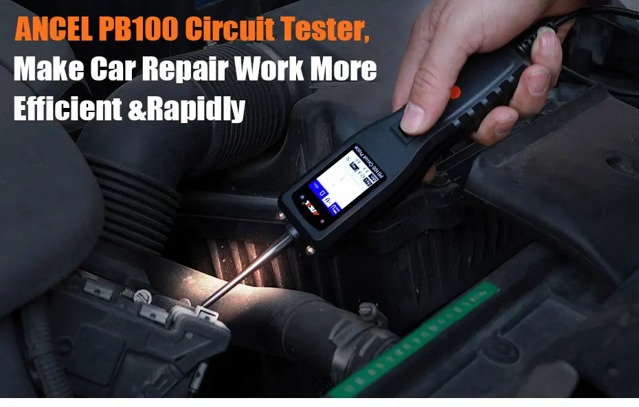
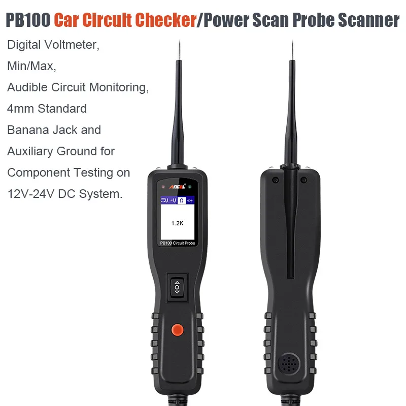
Ancel PB100 Automotive Circuit Tester Power Circuit Probe Kit Electrical System Mechanical Workshop Tools 24V 12V Power Scanner
The tool is the best electrical tester for reducing diagnostic time in all 6 to 30-volt vehicle electrical systems. After a simple hook-up of the tool to the vehicle’s battery, you can:
◆ Determine at a glance if a circuit is positive, negative, or open without having to reconnect clips from one battery pole to another.
◆ Test for continuity with its built-in auxiliary ground lead.
◆ By depressing the power switch, conduct a positive or negative battery current to the probe tip for testing the function of an electrical component without the use of jumper wires.
◆ Test for poor ground contacts instantly without performing voltage drop tests. The tool is also short circuit protected; its internal circuit breaker will trip if it becomes overloaded.
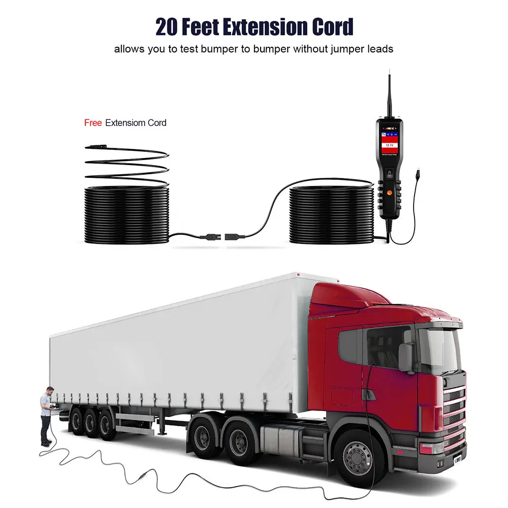
◆ Follow and locate short circuits without wasting fuses. The tool’s long cable allows you to test along the entire length of the vehicle without constantly searching for suitable vehicle grounds.
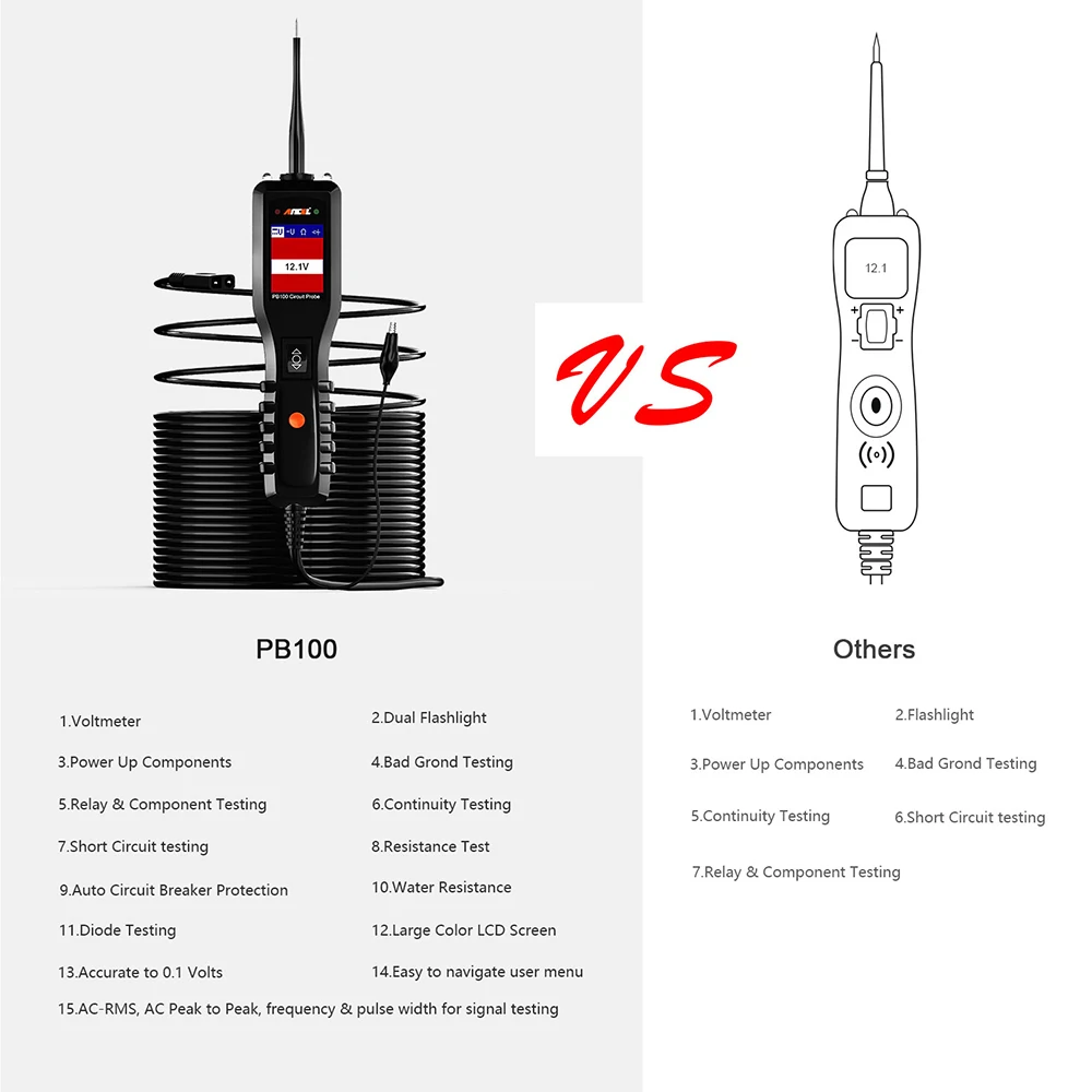
Why Choose ANCEL PB100 Electrical System Circuit Tester?

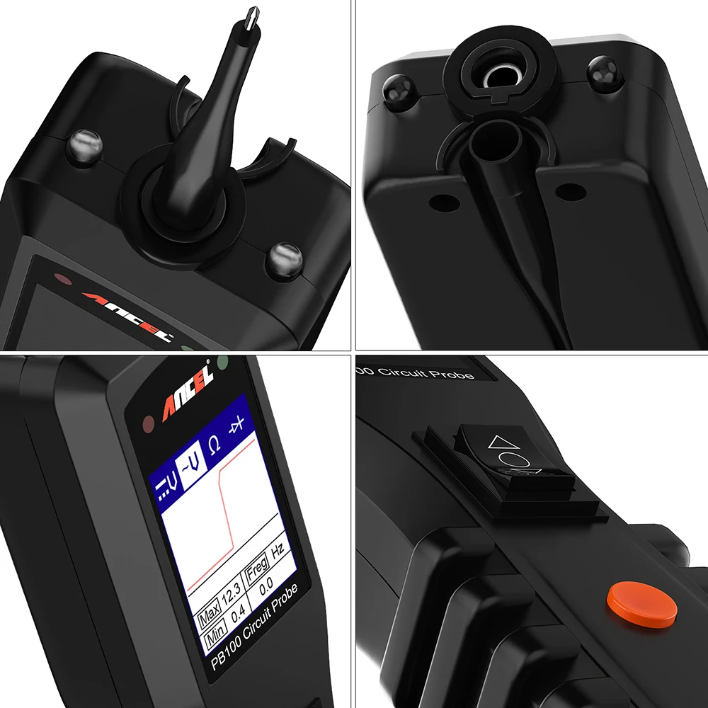
Voltage Readout
On the led screen at the front of the tool it will show you the battery voltage when hooked up. This can be used to determine a ton of things. You can even do a very quick check on the alternator, hook it up and start the car…Voltage should go from around 12.6 volts to 14.0 give or take. This is also useful if you have a situation where a power feed has a large voltage drop, when checking fuses you may see low voltage on certain legs etc.
Circuit Protection
The PB100 power probe has a built in 8 amp circuit breaker to prevent overloading and cooking a circuit. One thing to remember is unlike a standard test light this tool can send straight battery power down whatever you have it touching. Anytime you back feed a electrical circuit you need to know what you are doing. The breaker will protect the circuit, however 8amps is still enough to do major damage on the wrong wire.
Trailer Wiring
A recurrent source of frustration for technicians nationwide, particularly those who service trailers subjected to road salt or saltwater environments. The long 20-ft. leads allow you to make your initial hookup directly at the vehicle battery while easily accessing the trailer harness connector plug at the rear of the vehicle.
ANCEL PB100 Product Function:
1. Work Mode
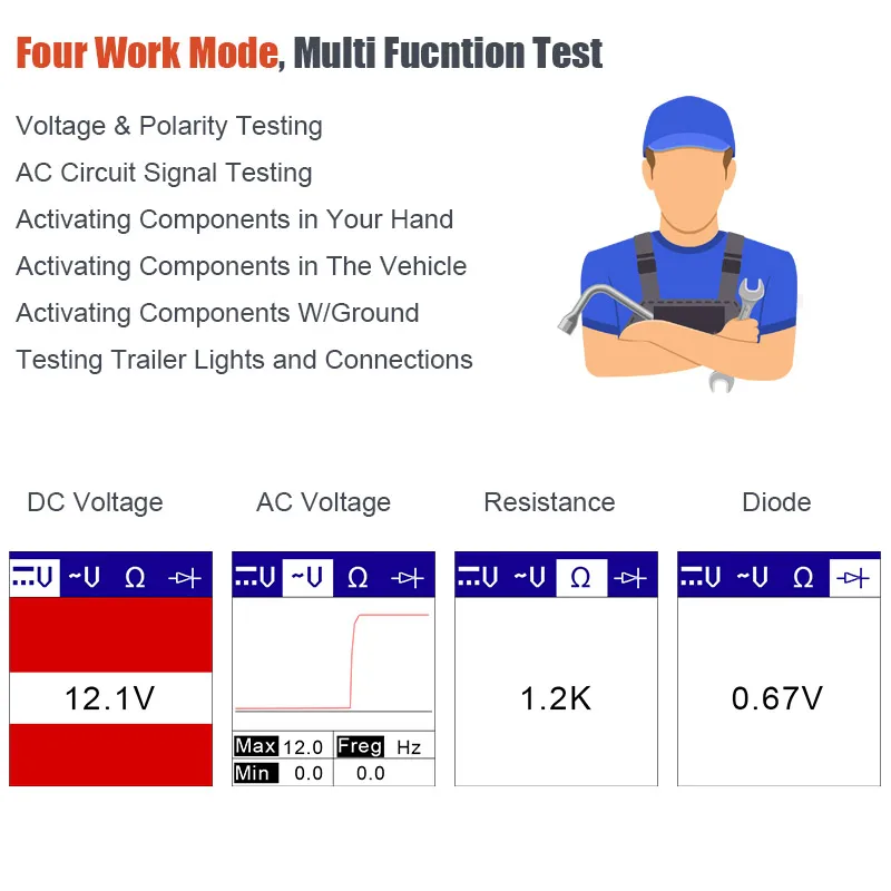
There are four modes to diagnose the electrical systems,which can be accessed by depressing the Mode Button and cycling through each one.
DCvoltage; ACvoltage; Resistance; Diode

2. Voltage and polarity testing
While the tool is in DC Voltage mode,contact the probe tip to a POSITIVE circuit.The red LED will light and the LCD displays the voltage with a resolution of 0.1V.A beep tone will sound.
If contact the probe tip to a NEGATIVE circuit, the green LED will light and the LCD displays the voltage with a resolution of 0.1V.A beep tone will sound.
If contact the probe tip to an OPEN circuit, neither of the LED will light.

3. Circuit Continuity Testing in Resistance mode
While the tool is in Resistance mode,using the probe tip with chass is ground or the auxiliary ground lead,continuity can be tested on wires and components attached or disconnected from the vehicle's electrical system.When the probe tip is contacting a good ground,the LCD will indicate"0.0Ω" and green LED wiil be on,A beep tone will sound.


4. Activating components in your hand
While the tool is in DC voltage mode,by using the probe tip in connection with the auxiliary ground lead, components can be activated right in your hand,thereby testing their functions.
Connect the auxiliary ground lead to the negative terminal or ground side of the component being tested. Then contact the probe tip to the positive terminal of the component,the green LED should light,indicating continuity through the component. While keeping an eye on the green LED,quickly press and release the power switch forward. If the green LED went out and the red LED came on,you may proceed with further activation. Rock the powers witch for ward and hold it down to provide power to your component. With the power switch rocked forward, power will flow from the
positive lead on the battery into the probe tip, through the tip into the component’s
positive terminal, into the component and out of the component, through the auxiliary ground lead and back into the tool, and back to the vehicle’s battery’s ground.
(1) Press the power switch forward to activate the bulb.
(2) Contact the tip to the positive terminal of the bulb.
(3) Connect the negative auxiliary clip
If the green LED went off at that instant or if the circuit breaker tripped, the tool has
been overloaded. This could happen for the following reasons:
◆ The contact you are probing is direct ground or negative voltage.
◆ The component you are testing is short-circuit.
◆ The component is a very high current component (i.e., starter motor).
If the circuit breaker is tripped, reset it by waiting for it to cool down (15 sec.)

5. Activating components in the Vehicle
While the tool in DC Voltage mode, contact the probe tip to the positive terminal of the component, the green LED should light, indicating continuity to ground. While observing the green LED, quickly depress and release the power switch forward. If the green LED went out and the red LED came on, you may proceed with further activation.
If the green LED went off at that instant or if the circuit breaker tripped, the tool has been overloaded. This could happen for the following reasons:
(1) The contact you are probing is a direct ground.
(2) The component you are testing is short-circuited.
(3) The component is a very high current component (i.e., starter motor).
If the circuit breaker is tripped, reset it by waiting for it to cool down (15 sec.)
WARNING: Haphazardly applying voltage to certain circuits can cause damage to a
vehicle’s electronic components. Therefore, it is strongly advised to use the vehicle
manufacturer’s schematic and diagnosing procedure while testing.
NOTE: When powering up components, you can increase the life of power switch if
you first press the switch, then contact the tip to the component. The arcing will take
place at the tip instead of the contacts of the switch

6. Testing trailer lights and connections.
While the tool in DC Voltage mode, clip the auxiliary ground lead to the trailer ground , probe the contacts at the jack and then apply voltage to the probe tip. This lets you check the function and orientation of the connector and trailer lights.
If the circuit breaker tripped, that contact is likely a ground. Reset the circuit breaker by letting it cool down for 15 seconds.

7. Signal Circuit Testing
For example,you suspect there is a problem with your M.A.P.?sensor circuit,then follow the procedure involved with testing this sensor:
Set the tool in AC Voltage mode,using the probe tip with chassis ground or the auxiliary ground lead.
Connect vacuum pump to MAP sensor.
Contact the probe tip to the MAP sensor positive terminal and observe the LCD readings which should be a sine wave in normal condition.
Apply vacuum
Release vacuum and observe the LCD readings

8. Activating components W/Ground
While the tool in DC Voltage mode, contact the probe tip to the negative terminal of
the component, the red LED should light. While observing the red LED, quickly depress and release the power switch rearward. If the red LED went out and the
green LED came on, you may proceed with further activation.
If the green LED went off at that instant or if the circuit breaker tripped, the tool has been overloaded. This could happen for the following reasons:
(1) The contact you are probing is a direct positive voltage.
(2) The component you are testing is short-circuited.
(3) The component is a very high current component(i.e., starter motor).
If the circuit breaker is tripped, reset it by waiting for it to cool down (15 sec.).
WARNING: With this function, if you are contacting a protected circuit, a vehicle’s fuse can be blown or tripped if you apply ground to it.

Four work mode, multi function test
Voltage and polarity testing
AC circuit signal testing
Activating components in your hand
Activating components in the Vehicle
Testing trailer lights and connections
Testing trailer lights and connections
ANCEL PB100 Car Battery Tester Functions:
1. Power injection, measuring, ground testing, polarity checking, continuity testing and component activation.
2. Read the AVO meter, voltage, current, and resistance.
3.Energize the electrical components, such as the cooling fan, relay etc.
4. Activate the components
5. Determine the positive, negative and open circuit.
6. Test the bad ground contacts, follow and locate short circuits without wasting the fuse.
7. Test the continuity of the power switch, relay and diode.
8. Protect the tool from overload.
9. Allow you to work in the dark area by using the built-in head light.
10. Test along the vehicle by the long cable.

ANCEL PB100 Power Probe Specifications
◆ Display: TFT color display (160 x 128 dpi)
◆ Operating Temperature: 0 to 60C (32 to 140F)
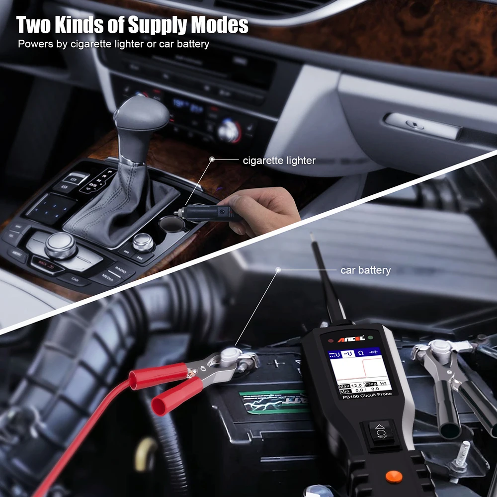
◆ External Power: 12.0 or 24.0 V power provided via vehicle battery
◆ DC voltage range: 0-65V +1digit
◆ Resistance range: 0-100 kΩ
◆ Frequency response of tone pass through 0Hz to 10Khz.
◆ Circuit Breaker
◆ Rating current: 1-10 Amp
◆ Testing Standard:
100% current: Hold > 1 hour
150% current: trip in one hour
200% current: trip in 3-30 seconds.
300% current: trip in 0.5-4.0 seconds.

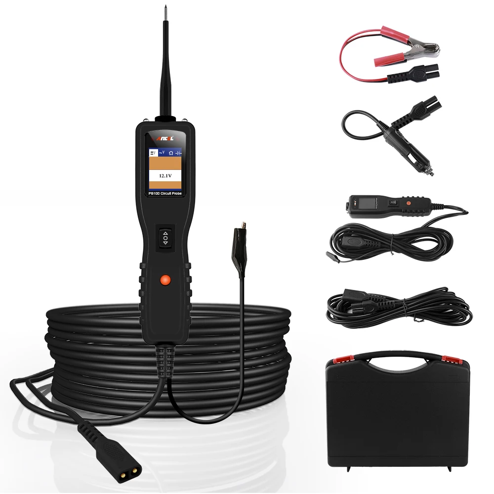
Ancel PB100 Package List
1*ANCEL PB100 Power Scanner
1 *Rugged Blow Molded Case
1 *20ft. Extension Cable
1 *Probe Tip
1 *Battery Hookup Clips
1 *Cigarette Lighter Adapter
1 *User Manual